|
| Pic: Stefan Ruitenberg |
Hello there!
It’s going to be a great shame that the BR Engineering SMP Racing BR01 LMP2 car won’t be able to race from 2017 onwards, due to new chassis regulations from the FIA and ACO, whereby SMP was not chosen. Having introduced the car in 2015, the year before really saw the project take off in the design and manufacturing side of things. Let’s take a closer look.
At the start of 2014, right the way to February in 2015 saw the car built, developed and even tested, albeit there was very minimal running time. Going back to when the car got the green light, SMP was able to draft in legendary designer Paolo Catone who penned one of the greatest LMP1 cars, the Peugeot 908.
One of the rules in LMP2 state that any chassis builder must be able to sell your products to a customer team. Even though Strakka and Dome dodged that bullet through a loophole with its S103, SMP wanted to stay true to the regulations, “We wanted to play things properly. We wanted a car that can suit all types of drivers in the spirit of the regulations.” says Catone when he was speaking to Lawrence Butcher in Race Engine Technology Magazine (RETM). Although Catone was able to find that loophole, he felt it was not right for the team to go down that direction, such as Strakka Racing did.
SMP wanted Catone to develop the car by himself, which for anyone is a big undertaking. “when I undertake projects such as the BR01, I have to use my network of supplies and people to do the design work. I have built up a reliable network of manufacturers who are very competent and reactive to my needs” says Catone in RETM. One of these companies was Fondtech, who was able to design and develop the aerodynamic package. Sub-contractors were key for SMP Racing in manufacturing and design of its new LMP2 car.
 |
| Pic: Stefan Ruitenberg |
Chassis
Starting off with the chassis, the car uses carbon fibre composite tub and outer bodywork panels, of which have been made by Italian company ARS Technology. The key areas where BR Engineering looked at was the front bulkhead and driver cockpit, of which has been developed to work outside of the box, on which is explained later.
The SMP BR01 does share some similar areas to the other P2 cars in races with, such as the Strakka Dome and Ligier JS P2, of which all use a high level of detail to fine tune the overall balance of the car. Some of the key areas they have looked at are the front splitter, side turning vanes and rear deck.
“Our car is very tightly packaged, as we wanted it to be as small as possible, so that weight was down, as well as giving a suitable foundation for the aerodynamics.” Says Catone. He later hinted “that there are very little compromises” which he is very happy about as said in RETM.
Catone wanted his prototype car to be able to run at the front of the pack, and not just with professional drivers. This means that drives of all shapes and sizes must be able to race it. This, of course, needed some neat design features to be able to make Catone’s idea come true.
To achieve this, the car needs to be comfortable, and so BR Engineering had to modify the survival cell at best to improve the accessibility and visibility. This is something all drivers want but can give the car a compromise in the aerodynamic department. On the SMP car, the cockpit is bigger to the one used on the Ligier JS P2 and Oreca O5, but amazingly it's lower.
One key area the team improves was the windscreen surround, which is much thinner. While this gives the driver better viewpoints, the structural integratory was the same thanks to some neat ideas with the carbon fibre honeycomb structure.
Another area where SMP went to town was the doors, which is actually bigger than the regulations states. Cantone says “Driver change in key” so opted to use bigger doors to help the drives by getting into and out of the car. This approach means the teams can get quicker pit stops, which no compromises have been made with the aerodynamics of the bigger doors. Although the doors took longer to manufacture, and are more expensive, the car is not compromised in the area.
For the rear, steel composite tubes come from the back of the survival cell to the spacer in between the gearbox and engine, which makes it a type of hybrid chassis design.
 |
| Pic: Stefan Ruitenberg |
Suspension systems
While the chassis stands out from current LMP2 cars, the suspension, in fact, does too. The design on the Strakka, Oreca and Ligier cars have torsion bars with a heave spring. The suspension up front on the BR01 is coil springs mounted horizontally in the bulkhead. There is a myth that this can compromise the tyre contact patch, but there is zero difference here.
The only place it will differ is the damper unit would become a damper spring unit, so it’s a bit bigger in diameter to the ones used within a torsion bar set up. I can confirm that this concept is harder to package in the bulkhead, with the steering rack, column, universal joint and a large array of sensors here too.
While a torsion sprung front end is more expensive, the SMP Racing boys opted to use coil springs as it's much cheaper. And due to the car being sold to customer outfits, the team had to keep costs down as low as possible. The LMP2 cost cap is around the £380,000 mark. And to build, design and optimise a car under this is by no means an easy task.
“I like to keep things simple, so teams are able to fix things. What’s the point of a racecar which is hard to repair and work on?” Catone asks. He later adds “coil springs are much quicker to set up too but weight more in the process,” he said in RETM.
For the back end of the car, the car uses coil springs too but laid on top of the innovative transmission casing, on which more later. The back end shows a relativity flat design, with push rods coming from the machined uprights to the bell cranks, which turn the forces 90° into the heave spring. The team has also applied the third element to help with other chassis movements. Catone never stated them, so could be for pitch, warp or even aero load. This set up is the same to what’s used on the other LMP2 cars, except the system is mounted lower due to the chassis and floor design. So, the biggest gain here on the BR01 is lower CofG.
 |
| Pic: Stefan Ruitenberg |
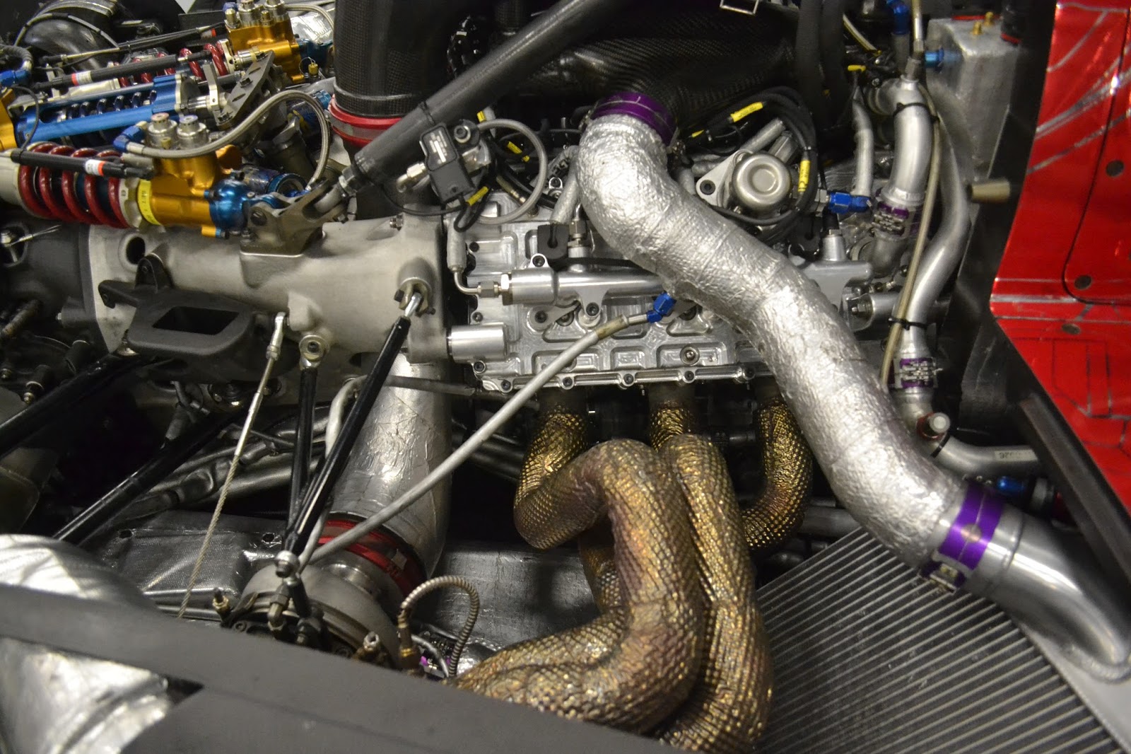
Drivetrain changes
When the BR01 project began way back in 2014, there was a large array of possible engines to use as the powertrain. As the technical regulations state, your chassis must be able to carry two engines. And for BR Engineering they went for the very popular Nissan VK45DE unit, and the Judd HK 48. Starting off with the Nissan VK engine, which is the one SMP recommend, and the one which all of its customers use. The engine is a V8 with a bank angle of 90°. It has a placement of 4494CC. The engine weighs 145kg with a bore and stroke of 93mm x 82.7mm.
With a 40mm air restrictor, the engine can produce 450bhp at the top of the rev range. While some teams have the turbocharged HPD unit, the Nissan unit is naturally aspirated, giving it a lot of low down grunt. But to meet the regulations, the chassis must accommodate two units. So BR Engineering just went with the two most used units. The chassis only needs minor changes to house the Judd HK 48 engine. With the engines, you can have sourced information and parts from either Gibson or Oreca. For the Nissan engines, they have parts sourced by Gibson Engineering, thus providing one of the most reliable engines in the LMP2 field.
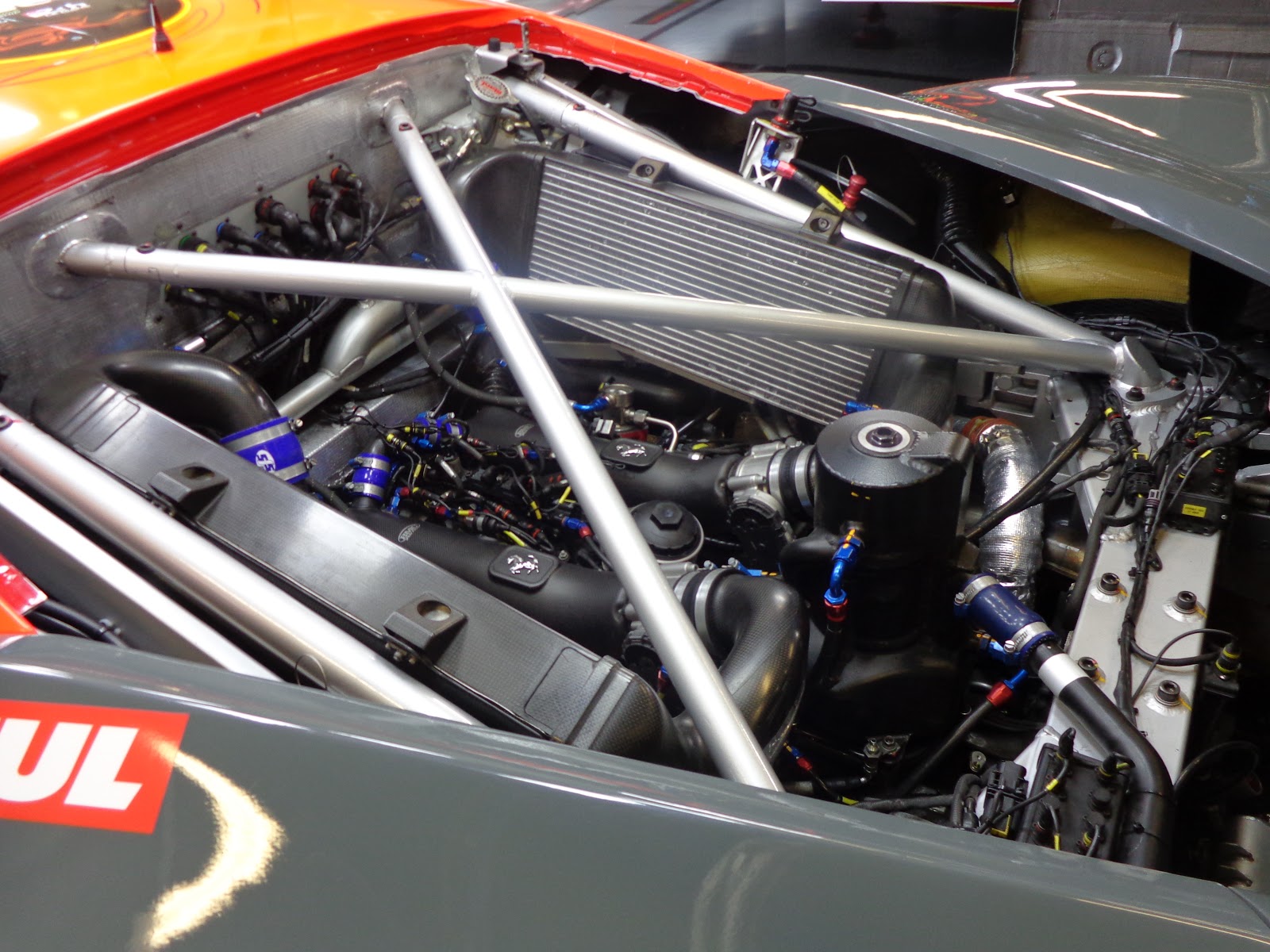
Change of fundamentals
With lots of supplies helping out with the car, such as Fondtech doing the aerodynamic package, both high and low downforce options, BR Engineering got Paolo Catone to design the transmission casing, and to improve on the existing off the shelf units.
While all the other teams use off the shelf Hewland or Xtrac transmissions. Who use off the shelf internals and casing. Both of these gearbox manufacturers are well proven and have bullet proof reliability. SMP felt they could do better with the case design.
When you look at the case designed by Mr. Catone, you can see how it completely eliminates the bell housing, which is a big weight saving element to the design. It also saved quite a bit of cost cut too. The design only has a small spacer in-between the gearbox and engine.
As Catone says “The height of the 6-speed casing is down to me, as we wanted to run the rear deck lower for better performance in the aerodynamic department.” He later adds “The height of the casing is pretty much the thickness of the back end” both of which were stated in RETM.
With the small case, the pick-up points for the wishbones are closer together, with the push rod arm going through the pair of them. The material used for the casing is magnesium, where most are aluminium. The use of magnesium was down to lightness but does offer a small compromise in the structural integrity of the case. The loss here is only very small.
For the uprights, the team has also designed them too and are CNC’d from Aluminum. The design also sees a simple approach being taken, which has also helped to cut costs. The brake set up sees 6 piston callipers all round with vented discs and carbon brake ducts.
 |
| Pic: Stefan Ruitenberg |
Aerodynamics
To design the aerodynamic package, Italian firm Fondtech was drafted in by Catone for the job. He says “I knew the wind tunnel was very reliable, and the same goes for the CFD development Fondtech did for us. You have a lot of companies offering CFD but I felt it was pointless to have one person or company looking at the wind tunnel and other at the CFD. If there were any problems, one company would simply tell the other that their part was no good and vice versa, so Fondtech did both the CFD and wind tunnel work” said in RETM.
He later adds “I am old-fashioned, and for me, the wind tunnel is the best way to go. The split between CFD and wind tunnel development was about 25-75 per cent” He said in RETM.
From looking at the car, the car does look quite stable through the fast corners of Daytona banking to the magnets and beckets at Silverstone. The aerodynamic performance looks to be safe, and a great all round package.
If we look at the front bodywork, Fondtech opted for a low nose design, which is similar to the Dome S103 and Oreca 05, but differs to the high nose on the Liger JS P2.
Unlike LMP1, LMP2 chassis builders must have a homologated aerodynamic package, with one low drag package being used at Le Mans only. These kits are capped at £10,000, so in theory, the LMP2 aerodynamic package is a compromise for all the class runners.
Most of the design work was focused on the front nose structure, where the team had nine different options, with almost twenty types of the splitter in use.
In the end, the nose has a stepped motion, with carbon turning vanes filling in the space either side of the nose to the wheel arches. Like a normal prototype car, this bleeds air via the side turning vanes, which on the BR01, are very JS P2 influenced.On the high downforce package, four twisted vanes are used in the side pod. But for low drag, these are taken away, providing less downforce, but drag in the process. A must at Le Mans.
At the rear, the setup shares some conventional ideas with normal prototypes. For the rear wing set up, the design sees a twin main plan set up in a set of end plates, with a sawn neck pylon from the dorsal fin. One area where all LMP cars benefit is from side force through cornering. Through cornering, the fin becomes a cambered wing which produces downforce. But as the load comes from the side, it’s side force which can dramatically produce more grip through cornering.
But the area where it does differ is the rear deck, which explained earlier is much lower thanks to the small transmission casing. The flow patterns here are somewhat better to the rear wing, due to less obstruction from the rear engine cover.
Different approach
When contractors were used to helping in the design or manufacturing process, it was difficult times due them not receiving payment from SMP Racing, which saw team boss Boris Rotenberg’s bank frozen. As Catone recalls, “We could not pay for things, and we even had a case of having a payment going back to the supplier as the bank sent it back. We asked the supplier why they had not started work and they said they have not been paid. It was then we discovered that the bank was just sending payments back, but not telling anyone they had done so. These problems meant we had some delays in the delivery of parts, so while the idea was to finish by November, as that is when the supplies are less busy, in reality, it overran and then supplies were overloaded with Formula One business. With those problems, it meant that it was not until February 2015 that we finished the first car. It was really complicated” he states in RETM.
If you want to build a quality race car in a year from scratch, you want the operation to run as smoothly as possible. And payment delays really did affect the SMP Racing boys. Due to this hurdle, SMP never really got the track time to test its new product, and to iron out any gremlins.
The debut race for the BR01 was at Le Mans in 2015, where the top car finished 14th place overall, that’s 6th place in class, which for a new car, hardly tested, was a fantastic result.
With the different approach of individual companies helping make the project happen, it almost stabbed them in the back with several delays occurring. But where credit is due to BR Engineering, the team pulled out all the stops to make a customer car which turns out to be quite quick in the WEC and ELMS championships. The team is always learning, so expect good things to come off the car.
Conclusion
With the help of outsourcing parts from well-proven supplies, the BR Engineering team was able to get the car made in time for 2015 WEC and ELMS seasons. With a shadow of a doubt, without the key supplies, Catone used, the car would not have been ready in time. While selling the car to teams, the company doesn’t make as much money as it would have liked. But as Catone says “It’s all about learning, and getting cars out there” which he has done.
The early days of the project meant that Paolo had to do a lot of research to get his head back to where it was with the 908 days. He had to look at a lot of current cars to see where the trend was going so that the BR01 car would be a success. He mostly checked the open top Oreca 03 chassis, which SMP was running in 2014.
But the biggest gain from the project is knowledge. The team has already hinted at a possible LMP1 car in the near future, but Catone was tight-lipped on that. We will have to wait and see if the next car from BR Engineering is as quick and beautiful as the BR01 is. BR02 anyone?
Acknowledgments
I would personally like to thank Race Engine Technology editor Lawrence Butcher for allowing me to reference his SMP Racing BR01 article in 24 Hour Race Technology Magazine 2016 issue. To read a more in-depth feature on the car, head over to www.highpowermedia.com.